This revision is from 2012/01/25 09:40. You can Restore it.
Original GEN_SubD-ThreadHighlights.pdf
Outline of the New Version(Edit)
- What is topology?
- Coffee cup & donuts.
- Purpose of being good with took:
- getting rid of undesired deformations. E.g., subsurfaced triangles.
- Adding desired deformations. - poles pinch, loops crease
- Ease of tool use (face select; animation deforming, etc.)
The Text(Edit)
1(Edit)


The Pole
Have a careful look at this Triangle image because it holds the key to mastering Sub-D modeling. Triangle is
the smallest element in a 3d model and by knowing how to solve Triangles you will make a big leap forward
as a 3d modeler. In fact, once you're through with this thread you'll be modeling like Bay Raitt! (No kidding!)
But first we must understand poles and before you read on make sure to forget what you have learned about
Poles! Here is another way of looking at it.
The (E) and (N)
Poles in general are not good for your Organic models however, you cannot avoid the 5 and 3 edges poles
and instead of being afraid of them why not try to understand them? Many beginners cannot advance to the
next level because of this blocka/ge (poles) and so they tend to fear them and
then Topology becomes difficult:f
and they fear that too. The 5 and 3 edges poles are very special poles, 6 and beyond are not special so you
can ignore them completely and since there are only two special poles we're going to give them names.
The E(5) Pole
The E pole is actually an “Extrude Pole†(E for short). When you extrude a Quad you will get 4 Es!
2(Edit)


When you extrude for the mouth, eye and ear you'll get 4 Es each. When you extrude for the arm/leg you
also get Es.
The N(3) Pole
When you model a nose you'll get this 3 edges pole and there is no way you can remove it because if you do
then that nose will not look like a nose and so it was meant to be there (Keep that in mind).
3(Edit)


I call this 3 edges pole “The Nose-Pole†(N for short). The Nose is a very special case in that you get “E†and
“N†next to each other, I call this the “EN†case. This “EN†situation will surfaces once you get into detailing
like the nose here. If you remove this “EN†you will remove the detail for the nose and in the image above I
have separated E and N with a Loopcut (more on this later).
Now why is the talk on Poles important? Poles control how things flow in your topology, have a look at the
image below and I'll get back later.

5(Edit)


The Es cannot be eliminated but the Ns can be. Since we can't really eliminate poles in general what we can
do is hide them and eventually they will be gone and that is the trick.
A good example of this is the NPoles for the forehead and the back (if you started with a Box that is). For the
forehead you hide it inside the eye and for the back you hide it inside the Ear. You do it via a method called
“UnPole†which I will go in-depth later. Now, just because you can remove NPoles doesn't mean you should
do it! Some Npoles are meant to be there like the Nose and when you get into detailing the muscles for the
human body you will get a lot of NPoles/EPoles since Poles control flows. A model with complicated flows will
have a lot of Poles and vice-versa.
I have argued with a much more experienced modeler about the Npole for the forehead. He told me having
the Npole there gives better control for the forehead. Now think about that for a moment.. we all know that
Poles make our meshs bumpy. Better control with a price and that price is “Bumpiness†and we all know that
the forehead is not 100% smooth! (Underneath is a skull) So yes, you can leave the Npole there for better
control of the forehead. Whether you should leave that Npole there or not is up to you. To say “Should I
remove it†is the same as saying “Can I use Ngon?†And the answer is always “If that is what you want, then
that is what you must do. There are no rules.†The picture will get clearer once I talk about smooth/bump
later.
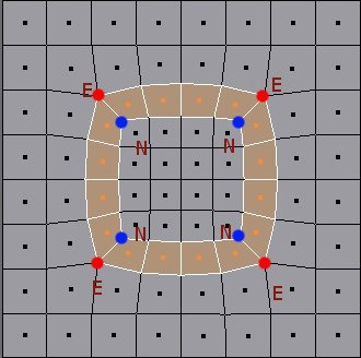
E
When you extrude a poly you instantly created a circular flow (dark orange in image). In some cases it's good
to have a circular flow with Es on the same lane (yellow), however in the case of a human head it's very bad!
6(Edit)


(A): According to the screenshots of human head from professional artists in my collection, this Loop for the
mouth is important. You cannot achieve this loop with both Es on the same lane so the trick is to move the
upper E to the left lane (B). The next time you see both Es on the same lane you can be sure that it will form
a Circular Loop.. If you remove (shifting it elsewhere) the upper E you will break the circular Loop like you
are seeing it here.
Instead of shifting the upper E I shifted the bottom and this is the result. Pay attention to poles because they
are your guide to better flows!
Quote:
when you extrude a quad you get EN not just E
Nice observation!
There are much more to Poles than I first thought. For example, when you extrude a POLY that has N pole as
one of its corners, you will convert that N into nothiing (no pole)!

8(Edit)


Earlier I said that when you see two Es on the same lane you can be sure that it will form a Circular Loop.
Here are two more images (below) to confirm that observation.
Pay attention to the Es because by shifting one back and forth you can achieve “predictable†flows! There are
no guesswork here.
You can use this dot/curve image as guide.
Key-Loop/Fill-Loop
Earlier in the “Form†thread I mentioned the Key and Fill concept and how you can use it in anything that you
do. Key-XXX/Fill-XXX, where XXX can be anything and in this case they are Key-Loop/Fill-Loop. When you
look at Edgeloop references out there what you are seeing is a bunch of Key-Loops for you to Fill in.
9(Edit)


In a KeyLoop stage Poles are close to each other and when you add in the Fill(s) they start to fall apart after
the tweak (It's difficult to keep them together after the Fill(s)). During the fill stage you can increase the
resolution for the KeyLoop that you're working on and while doing so you can move a specific pole away to a
place where you think it belongs. If you have been collecting wireframe references now is a good time to
open them and observe. Immediately you'll learn that all modelers are different in the way they place Poles.
There is no right or wrong but the general rule is: Don't put them in areas that deform and in the image
above (cyan dot) I put it there because I want it there. When I get into deformation and that area doesn't
deform well then I will do something about it but for now I will leave it there. I leave it there because I have
looked through many wireframes and I see that pole there... somewhere there and it doesn't have to be
exactly where.
If you're still afraid of POLES then have a look at this thread by Glen: BREAK THE SYMMETRY
In that thread Glen explains to us that the human faces are not 100% perfect. Why are we forgetting this
fact? The human faces have dimple, crack, holes and it's never perfect. Now just imagine that poles can be
used to represent these features. Hey, if someone say why you have a lot of Poles in your model, just make
up a story and say that this character had a car accident!
11(Edit)


If I learned something is to take a step back and analyse too what the basics are of edge loops and what the
functions are of the poles in addition to what you already explained. So permit me to present my findings
(and please don't hold back any critiques)
I found that there are 4 ways in which poles are produced on the mesh:
1) extrusion
2) spin quad/ spin edge
3) rip (help me out here, by lack of a better term. It is wath the V key does in Blender.. but I explain more in
detail later)
4) Knife tool
I also found out also that edgeloops may overlap on different ways without interfering with eachother
EXTRUSION:
After you invoke the extrude command, you may pull a 'limb' out the mesh, or confirming the command right
away, leaving an edgeloop on the mesh.
Something was said in the affect that a pole can not be elliminated? Well..you could do it like this:
After the cuts, you are left with 3 pairs of triangles that can be merged into 3 quads. The result looks a little
funky but if you elliminate another ADJECENT E pole you are left with a C loop
12(Edit)


funky, but if you elliminate another ADJECENT E pole, you are left with a C-loop
Edgeloops can coexist. So in this way you don't have to be afraid that there might be some dire consecuenses
that edgeloops you create might disrupt edgeloops that are already present:
As you can see, loops can touch eachother, intersect or be a part of each outer loop, which is cool. So this
means that you can form your eyes loop, mouth loop and pull a nose loop that intersect the mouth (or
mouth-nosetip loop) without a hassle. The nose loop could be converted in a C-loop with the technique I
mentioned above.
13(Edit)


Since C-Loop was brought up.
This incomplete head was modeled entirely in Blender from a BOX and it used the CLoop topology. If you're a
beginner I highly recommend that you start with this Loop because it's easy and can save you a lot of stress
since you're learning best of all you can create amazing result! As you can see from the image above, I have
gone far and still using that Loop. Now that I understand Topology after using the Cloop I can branch to other
Loops or even invent my own. Here is the Key:
14(Edit)

When I look at a wireframe I look for Poles because I can copy the topology using Poles as guide since Pole(s)
define a Topology, just look for the Poles. Last, do not be too obsessed with Topologies just read the SUB-D
Primer and you'll learn that having a clean/kick-arse Topology doesn't mean it will deform correctly during
animation. However for still images/Zbrush sculpting a CLEAN MESH is best. When you get into deformation
and things doesn't work out just use the knowledge here to change/adapt which is better than trying to learn
all the topologies that exist out there.
Poleless
This model is now 100% Poleless thanks to shahar2k at Wings3Ds forum who have shown me the trick and
here's the direct quote (for Wings3D):
Quote:
shahar2k:
a little experiment to try,
1 - take a model made out of 100% quads (any model that is smoothed once already for example)
2 - set all the edges to "hard"
3 - smooth the entire model once,
4 - select all "hard" edges and delete them,
5 - select all "isolated vertices" and delete those too
The Key idea is to subdivide your mesh and keep the subdivided version while deleting everything else. All the
EPoles will be converted into Ngons and all the NPoles will be converted into Triangles! To move Ngons around
is to move Epoles around and to move Triangles around is to move Npoles around which is one way or you
can do it directly after you subdivided. Once you have a poleless model you can start your Poleless quest, Bay
Raitt anyone?
Poleless conversion
Epole >
Ngon
15(Edit)


Epole → Ngon
Npole → Triangle
I don't know why anyone would want to do this and I guess the only way for me to find out is to get into
deformation later. The good thing about a Poleless model is that you can select an Edge's EdgeLoop and it will
run all the way from start to finish, nothing will be in its way (No poles).
Note: Don't try this in Blender
A Demonstration
Here is a very short and powerful demonstration before I get to the actual Technique (next post).
Take a look at (A) and what you'll see is the Loop I created on purpose. I want that Loop there but I also
want another one, look at (B)-Yellow Highlight. From what we know, 2 Es on the same lane will create a
circular flow and so I put a pole as pointed by the White Arrow.
Now I have it! BUT there is a problem. Look closely and you'll see that the original flow got broken (green) so
the question is: How do I create a secondary(B) flow while keeping the Primary(A)? The trick is to think one
step ahead.
One flow cannot go in both directions! You cannot have one flow that go LEFT AND RIGHT. To do that you
must split the main flow into two.
16(Edit)


So that one is reserved for the main flow while the second one is for, whatever you want.
Instead of splitting it into two I made 2 fills which gave me 3 flow.
As you can see, there are no guesswork here.
Quote:
Any chance of a look back there?
17(Edit)

modeling the nose is easy with Poly-by-Poly and for a box I still haven't figured out a logical way yet. If
you're looking for the best topo for the nose this image is not it. There are better flows for the nose out there
and I'll get to Toontje's post later.
18(Edit)


If you have a grid and you perform a spinedge somewhere, 2 N poles and 2 E poles will be produced. It
seems that in normal circumstances the number of E-poles is equal to the number of N-poles.
As you can see, after a spin, you are left with 2 loops like railroad tracks opposing eachother. I maybe wrong
here, but I found that you can follow the loops better if you look at the N-poles instead of the E-poles. You
see in the picture above that the edge loops get bent at the N-poles.
The cool thing about the spin egde command is that you can bend the loops anyway you like. One major
drawback is that each spin edge spawns a new loop.
19(Edit)


As you can see that if you intent to use spin edge to create loops, you will get this rather nasty side effect.
But you can use spinquands in situations to eleminate poles (just reverse the procedure above by spinning
the edge in the oppisite direction) or to correct edge flow, which I will explain in a later stadium.
Remember the simple extrusion that leads to a closed loop? Well, you can make a closed loop too with edge
spin and judge for yourself how much it differs from the extrusion method:
Here you have a closed edgeloop, but with side loops bordering its corners.
On a final note, you can collapse those side loops thus elliminating one N- and E-pole also like this:
20(Edit)

I deleted the edgeloop in the lower right corner by collapsing it. In Blender you should be able to delete this
loop, but I get an error saying that it is intersecting itself (must be a bug, because it clearly does not intersect
itself). So I merged the verts one at a time. Maybe it is possible to elleminate poles in general by collapsing
(unwanted) edgeloops? I'll have to experiment a little to find out if this is true for all situations.
21(Edit)


Today I'll be talking about mesh ripping. I don't know what the command should be called, or if there is a
similar command in another package than Blender. If anyone has a better name for it, I'm interested.
So, what's up? The tools that I'm explaining here are tools that have an effect on the topology because they
produce poles. I didn't quiete master the ins and out of this technique, but let me present to you what I
found out so far.
What is mesh ripping? With this tool (Vkey for Blender), you rip the mesh open by pulling at a vertex. In
Blender you should fill the hole it produces yourself.
The mesh above was ripped open at the upper N-pole. After that you may want to fill the resulting hole. In
these scenarios I will fill the hole.
So, like spin edge, rip mesh produces a pair of N-poles and E-poles. Like I said before, the direction of the
faceloop (I agree on the terminology too) is determend by the N-pole.
The resulting hole stands out like a diamond in the mesh. If you encounter such situations, and you a
meaning to eliminate poles, just merge those N-poles together to get rid of all the neighbourhing poles (thus
effectively reversing the mesh rip).
After a spin edge, you are left with pair of poles opposing eachother diagonaly. With mesh rip the poles are
opposing verticaly or horizontaly.
So far I have found these uses for mesh rip (topology wise that is):
1) Moving E-poles around (YES )2) Creating C-loops
Because of the lack of Ngons support in Blender, you have to manualy complement the mesh ripping
operation by using the cut tool and merge triangles into quads. But nevertheless, mesh rip is a very powerful
tool.
First, Creating C-loops:
The rip mesh tool is very flexible in conjuction with the knife tool. Depending on the method, you are left with
a single C-loop, or with a mirror pair of C-loops.
Creating a single loop:


23(Edit)


If you want to make a much wider loop, you must rip all the vertices in a row. You need to use the knife tool
to obtain the face loop. Depending of how you cut the mesh, the results will vary.
To obtain a single broader face loop:
Here I'll cut before I fill the hole, else there will be triangles in the corners
And then after filling the holes and cutting (and smoothing) you are left with one C-loop (by the way: I
assume that C-loop means C shaped loop and not closed loop).
24(Edit)


There is a number of ways to make a number of wacky face loops/ edge loops with this method, but i suggest
to keep it simple because simplicity and predictability is the name of the game here.
Lets try to make a a closed loop like in a extrusion:
25(Edit)


After the last operation you are left with this:
Wich is identical to an extrude operation of course. So let us keep in our back of our mind that the break
command and the extrude command is somehow related.
Now then, there are a lot of ways to finish of the break mesh operation with the knife tool, each producing its
own unique outcome.
Here I will demostrate the easiest way to use the knife tool, but it produces a mirror loop. This effect may or
may not be desirable depending on the situation.
After a break, fill the holes. You are left with 2 tris in each corner. Cut through this so the tris are doubled,
which means you can join them back to form quads (*).
And you are left with two overlapping C-loops:
26(Edit)

I've experimented a little with ways to complete the loop after a break, but the other results were a little
funky, like one c-loop being overlapped by two opposing c-loops.
You might think that a break is the oppisite of a vertex merge, but it isn't. In an all quad mesh, a vertex
merge can't be undone by a break.
But what a break does is removing one edge from a vertex! But a beak will add an extra edge on both its
corners. Armed with that knowlegde I will show you tomorow how to move poles around. Essentialy you are
adding an edge to the N-pole making a 4 edged vertex (normal quad) and you are removing an edge from
the E-pole, and at the same time you are adding an edge to a vertex outside the loop. It sounds like a mouth
full, but is just 2 simple actions.
27(Edit)


Earlier in my first post I showed you the Triangle image and told you that it held the key to mastering Sub-D
modeling.
The top row is what you have been living with and the bottom row is the UnPole technique. Combine this
technique with Spin Quad (plus the knowledge on Poles) and you have just mastered SUB-D modeling! Here
is another way to solve the Triangle.
Keep in mind that I did not invent any of the above I am only giving it a name and raising awareness
(especially the bottom row in the first image). Now that you can solve Triangles you can turn a messy mesh
into a good looking mesh! First let's look at the SpinQuad and Unpole.
Note: You need to know the above if you're planning to model in Blender since Blender produces a lot of
Triangles.
SpinQuad/UnPole
SpinQuad is a very powerful technique that can change a flow in an instance. All you need to do is select two
faces and Spin them.
28(Edit)


There are two problems to this technique and they are:
1: The mirror effect.
2: The NPole!
These two problems can be solved by unpoling the Npole and once that Npole is gone the rest will be gone.
I look at Unpole as a technique to clean up the mesh (beside shifting poles).
There are two ways to create/change a flow and they are:
1: From a pole perspective
If you want a pole at a specific location then do not use SpinQuad since it's difficult to visualize the result in
your mind. By knowing that two Es on the same lane will create a Circular flow, then it's logical to do it from
a pole's perspective.
2: From a SpinQuad perspective
Use SpinQuad when you don't think much about Poles. Sometimes it's logical to use SpinQuad over UnPole
and vice-versa!
And last you can combine these two together. I'll get into Shifting poles next for now try and open one of
your messy meshs and see if you can look at it from a Triangle perspective.
29(Edit)


I will present to you some technique to move poles around. One can be done with the Break command, and
the other can be done with the Spin Quad command.
First the break command:
Let us take a standard circular egde loop/ face loop as the starting point.
A break normaly produces 2 E-poles. In this we have to break the mesh (/vertex) at a specific location so you
are not introducing an extra E-pole. The logical place to do that is where the N-pole is located at. But not only
you'll shift the E-pole, but the N-pole will come along for the ride. But this technique can only be done when
there are no 'fill loops' present, in otherwords, the E-pole and N-pole are in direct contact.
As you can see, E-poles that once was on the same edge loop, are now on different edge loops.
30(Edit)


Using Spin Quad:
There is a lot of possibilities here making the spin quad rather flexible. As stated before (I think), the spin
quad should be used more as a tweak tool. By moving poles around, you have total control over the flow of
the loops. With the spin quad, if you spin an edge that is connected to a N-pole, you'll get a pair of quads
that shares two edges. This will look like two tris, but don't be fooled and convert it into a quad.
Let's start from this situation:
This was achieved by performing a spin quad.
SomeArtist already showed an inginieus method to eliminate one pole by unpoling the N-pole. I guess this
can be done for any N-pole. One possible disadvantage is that your mesh will become denser.
In the image above, you have 2 loops that are joined at the hips. Here I shall show how to move the E-pole
around and thus effectively seperate these two loops. This method can be repeated to further drift these
loops apart.
31(Edit)


Moving E-poles around through SpinQuad (continued)
In the image above there you can see those two loops that are joined at the hip. To seperate them you can
spin the green of blue edges. Don't spin the red edge, otherwise you are just reverting to the original
situation (no loops) or if you spin twice both loops will flow in a oppisite direction.
The green loops are easy. When you spin it, the loop will seperate and drift diagonaly away. You may keep
repeating untill the loop is at the end of the mesh. Or you can unpole it or collapse it to get rid of it.
Maybe it is not apperant in which direction you should spin this quad/ edge. Just visualize that you have to
spin it so the edge will allign to the horizontal adges outside the loop. So in this scenario you should spin the
upper right green edge once counterclockwise and the result is this:

33(Edit)


I can actually lose my breath by trying to show you all the combinations so what I'll do is show you the key
ideas then from there you can experiment to find out. I might only show you one way but keep in mind that
there are many ways! It depends on how you want your mesh to flow and how you look at solving the
Triangle.
When you want to merge two Es onto the same lane all you need to do is collapse the edges.
Moving the E (Rotating)
An E Pole has 5 edges and all you need to do is take one of the 5 edges and rotate it, that is in theory. In
practice what you do is delete it which will remove the E pole and you are left with an
Ngon. Rebuild the Ngon and there you have it...
Triangulate
34(Edit)


The combinations are endless once you turn a Quad into a Triangle. Look below:
The same key idea can be used in reversed:
Note: There are 8 images for this post
Toontje brought up SpinQuad and there is something interesting in it when you compare it with the Wrinkle
technique which is used for wrinkle effect but it can also be used to create flow(s).
35(Edit)


The difference is in the poles. Also, earlier I said that the Spin Quad are not logical well, after looking it a little
closer I can now say that it's very logical!
When you about to an spin edge or quads keep in mind that the green dots will be converted to Epole and
that the Orange dots will be converted to Npoles.
36(Edit)


In my previous post there is a matter left about the blue edges. This has to be spun COUNTER CLOCKWISE
always. The end effect is that the loop drops one position/ row. But in between the spin quad action will look
like a mess. Delete the lone vertex. What this realy is, is two quads sharing two edges. By deleting this vertex,
and filling the hole up, you are converting these 2 quads into one quad.
Ofcourse after smoothing and stuff the result will be:
37(Edit)


Indeed you might have noticed only a vertical shift. You can shift it verticaly too by spinning another edge. But
like SomeArtist said, I can lose my breath explaining all possibilities. As long you get the picture.
Next I'll explain the cut tool. I've discovered that the cut tool gives very unexpected results. You cannot just
simply cut away in your mesh and expecting a nice edge loop. But I found a method to correct that using the
magical but less understood Spin Quad again. With this method, you are left with a totaly clean face loop that
you can use for a number of things like fine detailing (veins and such)
But I'll continue later.....
05-06-2006, 11:43 PM
#32
Toontje
Join Date: Jan 2006
Location: Bonaire N.A.
Posts: 46
Bachelor/ Ingenieer
Cut/ knife tool
This one is very tricky and I doubt that someone discovered the fundemental flaw of the cut tool, otherwise it
would have been mentioned long ago. That is perhaps why I was never able to define muscle shapes with the
cut tool in the past.
I gather I don't have to explain what the cut tool does. But I don't know if it works the same for all packages.
But here it goes:
With the cut tool you can cut faceloops/ edgeloops into your model. Most of the time you hear that you can
model small detail like veins easily with the cut tool, so let's do that.
After this I'll smooth it a little and select the centre edge loop. The centre edge loop is not really a continiuos
loop because it terminates at each N-pole.
38(Edit)


Lets pull this edge out to form a nice vein or something
So it looks like a nice method to add detail or loops to a model right?
WRONG!
First of all remember that I've said how face loops got bent? They bend at a N-pole! All face loops layered after
that one will get bent by the N-pole!
Let's take a closer look at the cut mesh:
39(Edit)


Observe how the face loop would get bent at the N-poles. Indeed there is a problem here: the location on
where the face loop would bend alternates on both sides of the highlighted edge loop. This will result in
multiple face loops running ammock on the surface of your model. When you try to use the edge loop cut
you'll see that the edge loop cut will snap unexpectedly on various location on the mesh.
Notice also that the bending side alternate at a moment that the cut changes direction on the clock. So if you
keep cutting in a C-loop or closed loop (like a normal extrude) or keep spiraling with the cut tool, there won't
be any side effects. But as soon you make a S-like cut then you'll have this problem.
So this explains a) Why nobody never experience problem while cutting simple loops (like eye loops, nose
loops) early on when box modeling and b) that's why you mesh gets messy if you want to cut details on your
surface.
Here I'll colour the face loops that are produced by this cut operation:
The knife tool was supposed to be some kind of wonder tool, a modelers dream, but here you see that it will
40(Edit)
pp
, , yreap havoc on your mesh leaving you with a heap of ugly and useless face loops.
But there is an elegant cure thanks to the obscure... or better said our hero: Spin Quad.
To end this post I want to remark that everywhere and everybody is talking about edgeloops. But in my
experience I see that the face loops is the dominant factor in terms of topology. Heck, every top modeler
seems to highlight face loops in their model even though they are wrongly talking about edge loops.
41(Edit)


Luckily there is a simple solution to this problem. Remember that things go wrong at the moment the the
N-pole bends the loop on the other side of highlighted edge loop? Well, let us identify those N-poles that
causes the problem.
Those edges that are blue should be spun. If the edge to be spun was preceded by a counterclockwise
direction change in the edgeloop, then it has to be spun clockwise, if it was preceded by a clockwise turn, then
spin it counterclockwise. HUH??? OK, for example, the first N-pole to be spun in the image above was
preceded by a "L" turn. When driving on this L-turn you are making a counterclockwise move, so the first
problem N-pole on the route should be spun clockwise. And vice versa.
When you spin those edges you have to perform the same corrections I explained a few post back. That is to
delete the lone vertex and then fill the hole and smooth afterward.
42(Edit)


And the result is only one face loop. To pick up where the problems started: Let's make a vein. Now we have
to perform an edge loop cut.
Compare this image with the image in the previous post. They almost look the same, but this edge loop is
truly continious. It doesn't bump against poles along the way.
43(Edit)

The topology/ mesh here is clean. Compare it with the previous vein example. The differences is hard to spot?
Just follow the highlighted edge loop. Follow each little segment. On both sides of a segment there supposed
to be one quad on either side. That is the case at the second example. But check the first example: in the
problem areas, 2 segments of the edge loop share one quad, making it look akward.
44(Edit)


EN the Grid
When you create a form your objective is to have a perfect grid this is why it's bad to introduce Ngon/Tris at a
form stage because you're not into detailing and for some reason beginners have a habit of detailing their
meshs when they're not ready. Look at this diagram carefully because what you are looking at is the answer
you have been searching for.
1: You are seeing a base grid (low res) and on top of it is another grid (high res).
2: The E and N, the key to local Loops/Detailing.
3: A very special case (Red quad) that allows you to unpole diagonally (Breaking the Grid) if you choose to.
4: A chance to completely make that Npole gone! (Moving it elsewhere that is. There is one situation where
you can make it completely gone).
Before you detail your mesh you must have PROPER flows and you do that by “ENding the Grid†(Introducing
the E and N because there is no other way). Also keep in mind that Unpole is not a detailing technique, but a
cleanup and flow-directing technique! Instead of saying “Now where should I unpole?†you say “Now where
should I EN the grid?†because that's what you are doing.
A Demo – Here's a demo to put things into perspective.
45(Edit)
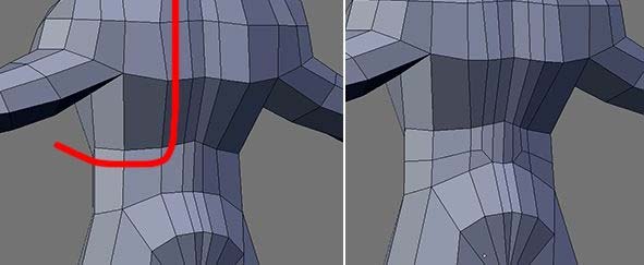


On the left of this image is a perfect grid (The Form) and I draw that red line to show you the flow that I
want. On the right I EN the grid to achieve that flow, that's it! That's all there is to detailing the mesh. But
wait, it doesn't look like a flow at all! In that case, tweak it, tweak tweak and tweak until it looks like one.
There I have it and now I hear you say â€This can't be it. This is too simple to be useful because I have seen
professionals create very complicated details on their meshs! With very complicated flows so there must be a
complicated solution.†Is that so?
Complexity is an illusion because all there is to complexity is simplicities. An artist is not a god and he doesn't
make things out of nowhere so now let's complicate things with simplicity!
46(Edit)


On the left I draw a very complicated flow and to do that you must EN the grid once again but there is a
problem. The problem is that the base grid's resolution is too low to have anything complicated so what I
must do is increase the resolution (Right, just like painting at resolution 320x240... not big enough to add in
super details).
Now I have the flow and you might say the flow that I created on the grid doesn't match with the one I drew!
In that case tweak tweak and tweak until it looks like it. One thing you should keep in mind is that you
shouldn't always try to match the flow that you imagined because what you are trying to achieve here is a
Key-Loop.
Now doesn't it look complicated to you? Keep in mind that I am not modeling the back of the human body
here just using it to demo the flows.
More on the next post and I'll respond to other posts later. (there are 6 images for this post).
Also, maybe Toontje or one of the mods can edit his post to make the image smaller so not to eat up the
screen.
47(Edit)


Forming the XT
Key 2: Instead of forming the C by letting it flows right into the Mouth you just go straight down. You will get
2 Poles as a result so you see, poles are not bad after all. CT and XT are all you need and from there you can
adjust and adapt. Looks like I won't be using the CT for realistic heads anymore after this thread is over. The
problem with the C Topology is the (Jaw?) I find it very difficult to control that area of the head and maybe
this is the reason why a lot are using XT since the grid makes it easier to tweak and define that area because
of the Npole.
Ngon/Triangle
There are two types of Ngon: Ngon with Pole(s) or without.
Ngon and Npole both starts with the letter “N†(coincident) and things just got easier because of this. Instead
of looking at surfaces (Quad/Tris/Ngon) we're going to look at it from a Pole(Point) perspective because when
you manipulate/deform a mesh you are manipulating the vertices/poles, not the surface (or face) itself.
Just to complete the naming:
QPole = Since the Q looks just like an “O†(Organic) we should call a vertex that has 4 edges connecting to it
a Qpole (Q=quad).
Xpole = 6+ Edges connecting to a Vertex. X = not wanted or bad.
So in total we now have: X, E, N, Q
48(Edit)


When we talk about Ngons the name “Stahlberg†comes to mind but do you really think he models with
Ngons? The answer is NO. If you really think deep about it, it makes perfect sense to say that he models with
Npoles.
When I look at things from a Pole perspective I don't care about Ngon/Tris/Quad/Edgeloop anymore because
it makes perfect sense not to think about it. We have been modeling with Poles (ENQ) and the surface that we
get is the result of our Poles' placement and the kind of Poles we use. Obviously, for truly round surfaces we
use Qpole as much as possible and it has been said that having good and nice looking Topology doesn't mean
it will deform correctly, when you model from a pole perspective you don't think about
Topology/EdgeLoop/Quad/Tris/Ngon. A model deforms correctly not because it has nice and clean Topo or
(quads) but because the poles are in the right place. When it comes to texturing, Tris and Ngons don't cause
problem the pole does and how you place it. I haven't looked into “The Boneâ€, “The UV†yet so I will save this
for future.
There are many ways we can look at a pole:
1: Poles are bad because they create non-smooth surfaces.
I was at this level before and nothing make sense. It was frustrating yet somehow I knew that Pole is the
answer.
2: Pole for Flow
Looking at it from this level things are starting to make sense but people still argue about
Ngons/Tris/Edgeloop... So...
3: The Pole
This will answer it all. At this level you don't think about the surface (Ngon/Quad/Tri/Edgeloop) but The Pole
(this doesn't mean you should abandon #2). The Pole and many of it together make up the surface so when
you control the Poles you control the surface and it is at this level that you will come to understand Stahlberg
and the power of an Npole.
There's more to the E and N Pole and I'll talk about it in the future for now do note that E/Npole is used for
terminating EdgeLoops (assuming that you are looking at it from a flow perspective).
49(Edit)

For local detailing and mesh optimization perspective I prefer the Npole(Ngon) since it gives greater control
over the Epole(Triangle) – image above. I'll get back to breaking the grid again after this