This revision is from 2010/10/25 23:21. You can Restore it.
(I didn't start this Wiki before I had watched several of these videos. I might someday catch back up on Lectures 1-5.)
TOREDO(Edit)
Lecture 1 - Introduction and lumped abstraction
- ...
Lecture 2 - Basic circuit analysis method (KVL and KCL mMethod)
- ...
Lecture 3 - Superposition, Thévenin and Norton
- ...
Lecture 4 - The digital abstraction
- ...
Lecture 5 - Inside the digital gate
- ...
Annotated(Edit)
Lecture 6 - Nonlinear Analysis
- Creates a device designed to send a signal over a garage door sensor
- Unfortunately, the thing sounds terribly, because it transmits non-linearly. The waveform gets distorted. Demo starts around 38:15
Lecture 7 - Incremental Analysis
- Fixes problem with Lecture 6's circuit. (Student solutions involved going digital, which is over-solving the problem in this case.)
- Non-linear curves are linear in a small enough segment. So what you do is "squish" and "bump".
- Squish = Attenuate the signal so that it has a smaller range
- Bump = Raise the minimum signal so that the swing is higher up on the response curve of the component
- Then you just amplify on the other end. Really neat.
- AKA Small-signal method
Lecture 8 - Dependent sources and amplifiers
- Reminder about circuit analysis:
- Composition (Thevenin/Norton analysis) can often simplify
- Node method is always there when all else fails. The "Workhorse"
- Amplification (aka Gain, Increase in signal strength, etc.), motivating examples:
- Greater noise immunity of stronger signal
- Cell phone, Antenna -> Low-Noise Amplifier
- Digital signal amplification (keeping it within tolerances
- Voltage-Controlled Current Source (VCCS), CCCS, CCVS, VCVS; Examples:
- Independent Current Source: Current source + a resistor, simply VR = IR (24:00)
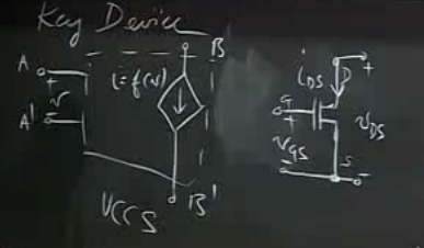
- Dependent Current Source (VCCS): Voltage source + Current source, I = f(V) (25:00)
- + Simplified circuit drawing for VCCS (27:00)
- V0 = VS - kRL/2 * (VI - 1)2
- (see 36:48)
- Very important equation for 6.002
- == an amplifier
- Curve examination (45:00)
- Real-life departure from equation (49:00)
Lecture 9 - MOSFET amplifier large signal analysis - part 1
- Review ends at ~9:00
- VCCS, e.g. MOSFET

- VGS < VT, D-S = like open circuit
- VDS < VGS - VT
- Resistive behavior, "SR Model"
- Digital
- Graphs @ 18:00, mentions, "A straight line is resistor-like behavior"
- VDS >= VGS - VT, D-S = like current source: ID = k/2 * (VGS-VT)2
- Shows curve for higher VGS, MOSFET saturates
- (Youtube comment says: "For a MOSFET, the saturation region is the region where the FET acts like a current source. It is the opposite name used for a BJT transistor. In a BJT this same region is called the linear region.")
- MOS Amp (34:00, diagram complete near 37:30)
TODO...(Edit)
Lecture 9 - MOSFET amplifier large signal analysis - part 2
Lecture 10 - Amplifiers - small signal model
Lecture 11 - Small signal circuits
Lecture 12 - Capacitors and first-order systems
Lecture 13 - Digital circuit speed
Lecture 15 - Second-order systems - part 2
Lecture 16 - Sinusoidal steady state
Lecture 17 - The impedance model
Lecture 19 - The operational amplifier abstraction
Lecture 20 - Operational amplifier circuits
Lecture 21 - Op amps positive feedback